

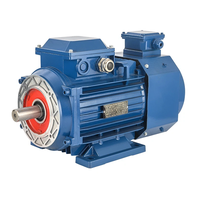
When using a frequency converter to control a YVF frequency variable motor, several key parameters need to be carefully set to ensure optimal performance, efficiency, and safety. As a trusted YVF frequency variable motor supplier, I have extensive experience in this area and would like to share some essential parameter - setting knowledge with you.
1. Frequency - related Parameters
Base Frequency
The base frequency is a fundamental parameter. It represents the frequency at which the motor is designed to operate at its rated power and voltage. For most YVF motors, the base frequency is typically 50Hz or 60Hz, depending on the power grid standard. When setting the base frequency on the frequency converter, it should match the motor's rated frequency. For example, if you are using a YVF2 Frequency Control Three - phase Asynchronous Motor with a rated frequency of 50Hz, the base frequency on the frequency converter should be set to 50Hz. This ensures that the motor can operate at its rated performance within the normal frequency range.
Minimum and Maximum Frequency
The minimum frequency determines the lowest frequency at which the frequency converter can output. Setting an appropriate minimum frequency is crucial, especially when the motor needs to run at a very low speed. For instance, in some conveyor belt applications, the motor may need to run at a slow speed to transport materials steadily. On the other hand, the maximum frequency sets the upper limit of the output frequency. It should be set according to the motor's maximum allowable speed. Exceeding the maximum allowable frequency can cause the motor to over - speed, leading to mechanical damage and reduced motor life. For an Inverter Adjustable 50Hz 60Hz Three Phase Motor, the maximum frequency should be set within the motor's specified range to ensure safe operation.

2. Voltage - related Parameters
Voltage - to - Frequency Ratio (V/F Curve)
The V/F curve is a critical parameter that defines the relationship between the output voltage and frequency of the frequency converter. In general, the voltage should be proportional to the frequency to maintain a constant magnetic flux in the motor. There are different types of V/F curves, such as linear, quadratic, and custom - defined curves. For most YVF motors, a linear V/F curve is commonly used. However, in some applications where the load has a special torque - speed characteristic, a quadratic or custom - defined V/F curve may be more suitable. For example, in a fan or pump application, a quadratic V/F curve can reduce energy consumption because the load torque is proportional to the square of the speed.
Output Voltage Limits
It is necessary to set the minimum and maximum output voltage limits on the frequency converter. The minimum output voltage ensures that the motor can start and run stably at low frequencies, while the maximum output voltage protects the motor from over - voltage damage. These limits should be set based on the motor's rated voltage and the requirements of the application.
3. Torque - related Parameters
Torque Boost
Torque boost is used to increase the output torque of the motor at low frequencies. When the motor starts or runs at a low speed, the stator resistance voltage drop becomes relatively large, which may reduce the motor's torque. By setting an appropriate torque boost value, the frequency converter can increase the output voltage at low frequencies to compensate for the voltage drop and improve the motor's starting and low - speed torque performance. However, excessive torque boost can cause the motor to overheat, so it needs to be adjusted carefully.
Over - torque Protection
Over - torque protection is an important safety parameter. It sets the maximum allowable torque that the motor can output. If the motor's torque exceeds this limit, the frequency converter will take protective measures, such as reducing the output frequency or shutting down the motor. This protects the motor and the mechanical equipment connected to it from damage caused by excessive torque.
4. Acceleration and Deceleration Time
Acceleration Time
The acceleration time is the time it takes for the frequency converter to increase the output frequency from the minimum frequency to the maximum frequency. A shorter acceleration time allows the motor to reach the desired speed quickly, but it may cause a large inrush current and mechanical shock. On the other hand, a longer acceleration time can reduce the inrush current and mechanical shock but may slow down the system's response. The acceleration time should be set according to the load inertia and the requirements of the application.
Deceleration Time
The deceleration time is the time it takes for the frequency converter to decrease the output frequency from the maximum frequency to the minimum frequency. Similar to the acceleration time, a shorter deceleration time can stop the motor quickly but may cause a large regenerative current and mechanical shock, while a longer deceleration time can reduce these effects. The deceleration time also needs to be adjusted based on the load inertia and application requirements.
5. Other Parameters
Carrier Frequency
The carrier frequency affects the smoothness of the motor's operation and the electromagnetic interference (EMI) generated by the frequency converter. A higher carrier frequency can make the motor run more smoothly and reduce the motor's noise, but it also increases the switching losses of the frequency converter and may cause more severe EMI. A lower carrier frequency reduces the switching losses and EMI but may result in a rougher motor operation. The carrier frequency should be selected according to the requirements of the motor and the surrounding electromagnetic environment.
Control Mode
There are different control modes available on the frequency converter, such as V/F control, vector control, and direct torque control. V/F control is a simple and widely used control method, suitable for most general - purpose applications. Vector control and direct torque control can provide more precise control of the motor's torque and speed, but they are more complex and require higher - performance frequency converters. The control mode should be selected based on the specific requirements of the application, such as the accuracy of speed control and torque control.
In conclusion, setting the parameters correctly when using a frequency converter to control a YVF frequency variable motor is essential for achieving optimal performance, efficiency, and safety. As a professional YVF frequency variable motor supplier, we can provide you with high - quality 2HP 5HP 10HP 20HP Variable Speed Electric Motor and comprehensive technical support. If you have any questions about parameter setting or need to purchase YVF frequency variable motors, please feel free to contact us for further discussion and negotiation.
References
- "Frequency Converter Handbook" by ABB.
- "Electric Motor Drives: Modeling, Analysis, and Control" by Bin Wu.


