

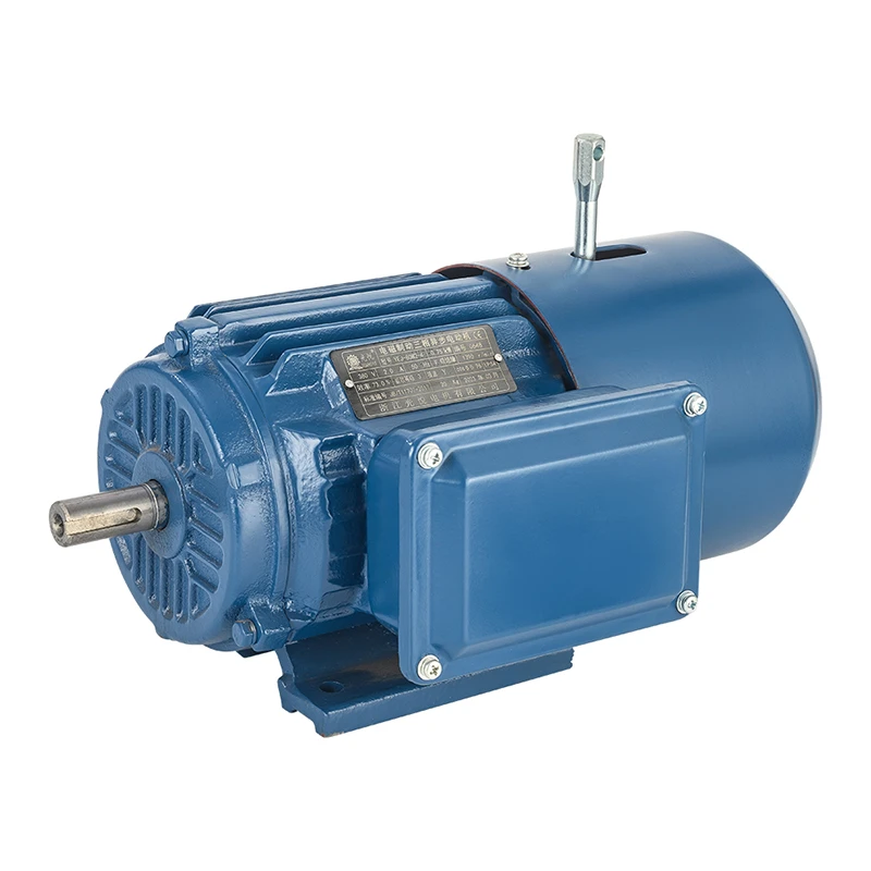
Hey there! As a supplier of 5.5KW Electromagnetic Brake Induction Motors, I often get asked about the materials used in the stator and rotor of these motors. It's a crucial topic because the materials directly impact the motor's performance, efficiency, and durability. So, let's dive right in and explore what goes into making these essential components.
The Stator: The Heart of the Motor
The stator is the stationary part of the motor, and it plays a vital role in creating the rotating magnetic field that drives the rotor. It consists of several key components, each made from specific materials.
Stator Core
The stator core is typically made of laminated electrical steel sheets. These sheets are thin, usually around 0.35 to 0.5 mm thick, and are coated with an insulating layer to reduce eddy current losses. Electrical steel, also known as silicon steel, has high magnetic permeability and low core loss, which makes it ideal for this application. The laminations are stacked together to form the core, and they are often held in place by clamping bolts or welding.
The use of laminated steel helps to minimize the eddy currents that would otherwise be induced in the core when the magnetic field changes. Eddy currents can cause significant power losses in the form of heat, reducing the motor's efficiency. By using laminated steel, we can keep these losses to a minimum and ensure that the motor operates as efficiently as possible.
Stator Windings
The stator windings are made of copper or aluminum conductors. Copper is the preferred choice for most high-performance motors because it has excellent electrical conductivity and thermal conductivity. This means that it can carry high currents with low resistance, resulting in less power loss and better heat dissipation. Aluminum, on the other hand, is lighter and less expensive than copper, but it has lower electrical conductivity. It is often used in applications where weight and cost are more important than performance.
The conductors are wound around the stator core in a specific pattern to create the desired magnetic field. The winding pattern can vary depending on the motor's design and application, but it typically consists of multiple coils connected in series or parallel. The windings are insulated with a high-quality insulation material to prevent short circuits and ensure reliable operation.
The Rotor: The Moving Part
The rotor is the rotating part of the motor, and it is driven by the magnetic field created by the stator. There are two main types of rotors used in induction motors: squirrel cage rotors and wound rotors.

Squirrel Cage Rotor
The squirrel cage rotor is the most common type of rotor used in induction motors. It consists of a laminated core with conductive bars inserted into slots around the circumference of the core. The bars are short-circuited at both ends by end rings, forming a closed loop. The bars and end rings are typically made of aluminum or copper.
When the stator creates a rotating magnetic field, it induces currents in the rotor bars. These currents interact with the magnetic field to create a torque that causes the rotor to rotate. The squirrel cage rotor is simple, robust, and reliable, which makes it ideal for a wide range of applications.
Wound Rotor
The wound rotor is less common than the squirrel cage rotor, but it offers some advantages in certain applications. It consists of a laminated core with three-phase windings wound around it. The windings are connected to slip rings on the rotor shaft, which allow external resistors to be connected to the rotor circuit.
By adjusting the resistance in the rotor circuit, we can control the motor's speed and torque characteristics. This makes the wound rotor suitable for applications where precise speed control is required, such as in cranes, elevators, and hoists.
Why the Right Materials Matter
The choice of materials for the stator and rotor is critical to the performance and reliability of the motor. Using high-quality materials can improve the motor's efficiency, reduce energy consumption, and extend its lifespan. On the other hand, using inferior materials can lead to poor performance, increased maintenance costs, and premature failure.
As a supplier of 5.5KW Electromagnetic Brake Induction Motors, we take great care in selecting the materials for our motors. We use only the highest quality electrical steel for the stator core, and our stator windings are made of pure copper for maximum conductivity. Our squirrel cage rotors are made of high-strength aluminum alloy, which provides excellent performance and durability.
If you're in the market for a 5.5KW Electromagnetic Brake Induction Motor, you might be interested in some of our products. Check out our Braking Motor YEJ Series Cast Iron Frame 100HP, YEJ 460V 1700rpm Electric Motor for Driving Machine, and Motor 2.2kw Three Phase Induction Brake Motor. These motors are designed to meet the highest standards of quality and performance, and they come with a range of features and options to suit your specific needs.
Conclusion
In conclusion, the stator and rotor of a 5.5KW Electromagnetic Brake Induction Motor are made of carefully selected materials that are designed to provide optimal performance and reliability. The stator core is typically made of laminated electrical steel, while the stator windings are made of copper or aluminum. The rotor can be either a squirrel cage rotor or a wound rotor, and the materials used for the rotor depend on the motor's design and application.
If you have any questions about our 5.5KW Electromagnetic Brake Induction Motors or would like to discuss your specific requirements, please don't hesitate to get in touch. We're here to help you find the right motor for your needs and provide you with the best possible service.
References
- Electric Machinery Fundamentals, Stephen J. Chapman
- Electric Motors and Drives: Fundamentals, Types, and Applications, Austin Hughes


